¶ Gantry Definitions (ATM | Gantry)
The Gantry Wizard form allows the user to add new gantries and edit existing gantries.
¶ Accessing Form
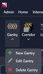
The Gantry Wizard can be accessed from the ATM ribbon tab.
- ATM Tab -> Gantry -> New/Edit Gantry

- Map Tab -> Add Device (New gantry only)

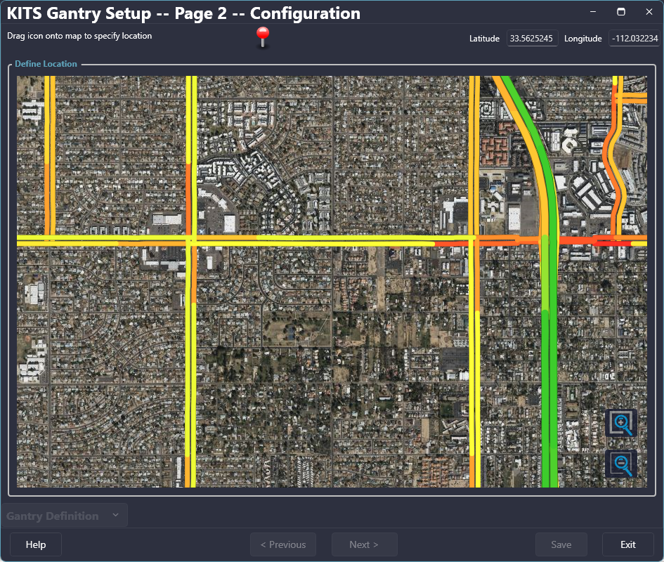
¶ Defining Gantry Location
When adding a new Gantry, the location can be set or edited from the 'Define Location' page of the wizard. If it is a new gantry and a pin has not been placed, click and drag the pin at the top of the form to the desired location. If a pin has already been dropped, it can be relocated by clicking on it and dragging it to the desired location.

| Field | Description |
| Zoom In | Zooms the map in towards the center of the map view |
| Zoom Out | Zooms the map out |
| Latitude | Latitude of the pin's location |
| Longitude | Longitude of the pin's location |
| Help | Opens the help file |
| Cancel | Cancels the gantry changes/creation |
| Previous | Goes to the previous page of the New Device Wizard (Page 1 is only accessible when Add New Device is used to open the wizard) |
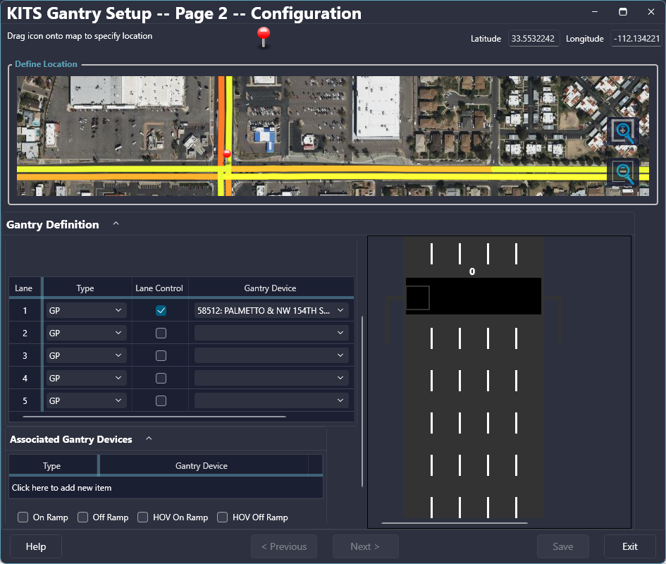
¶ Configuring a Gantry
After the pin has been placed the Gantry Definition section of the Wizard becomes available. The gantry's required attributes are outline in red. After completing the definition entry for a gantry, the Save button will be enabled allowing the user to finalize the gantry and close the Gantry Wizard. If Previous or Exit is selected before saving, any data entered will be lost.

| Gantry Parameters Fields | Description |
| Asset ID* | Sets the Asset ID of a gantry for identification |
| Name* | Sets the Name of a gantry |
| Lane Count | Sets the number of lanes that are defined for the gantry |
| Roadway ID | Sets the roadway references ID for the gantry |
| Segment ID | Sets the segment reference ID for the gantry |
| Enable Junction Control | Enables/Disables the ability to allow junction control scenarios to be set |
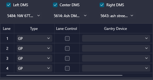
| Left DMS (Checkbox) | Enables/Disables the presence of a left side DMS |
| Left DMS (Drop Down) | Sets the Left DMS to a available DMS that is defined within the system |
| Center DMS (Checkbox) | Enables/Disables the presence of a center DMS |
| Center DMS (Drop Down) |
Sets the Center DMS to a available DMS that is defined within the system Note: Using a multi-window center DMS will disable the option for selecting individual DMS Lane Controls. See Configuring Lane Controls below. |
| Right DMS (Checkbox) | Enables/Disables the presence of a right side DMS |
| Right DMS (Drop Down) | Sets the Right DMS to a available DMS that is defined within the system |
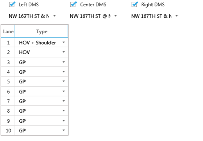
| Lane | Defined lanes starting with the left most lane as 1 up to the total number of defined lanes |
| Type |
Sets the type of each lane:
Note: Exit lanes are lanes which have a path of travel that does not require a merge, and traffic from that lane is no longer present at the next gantry. A freeway to freeway interchange ramp may be an example of this. The shoulder designation indicates wide shoulders suitable for traffic flow in rare or emergency situations. |
| Lane Control (Checkbox) | Enables/Disable the option to select an individual DMS for Lane Control |
| Gantry Device (Drop Down) | Sets the Lane Control DMS to an available DMS that is defined within the system |
| Associated Gantry Devices Fields | |
| Type |
Adds a device type to be associated with the gantry: CCTV Ramp Meter Detector Station |
| Gantry Device (Drop Down) | Sets the device to an available device of the type that is selected |
| On Ramp | Enables/Disables the display of an On Ramp |
| Off Ramp | Enables/Disables the display of an Off Ramp |
| HOV On Ramp | Enables/Disables the display of an HOV On Ramp |
| HOV Off Ramp | Enables/Disables the display of an HOV Off Ramp |
| Service Road | Enables/Disables the display of a service road |
| Cross Street Name | Sets a label for the closest cross street name |
| * - Minimum required attributes for an Gantry to successfully be created. | |
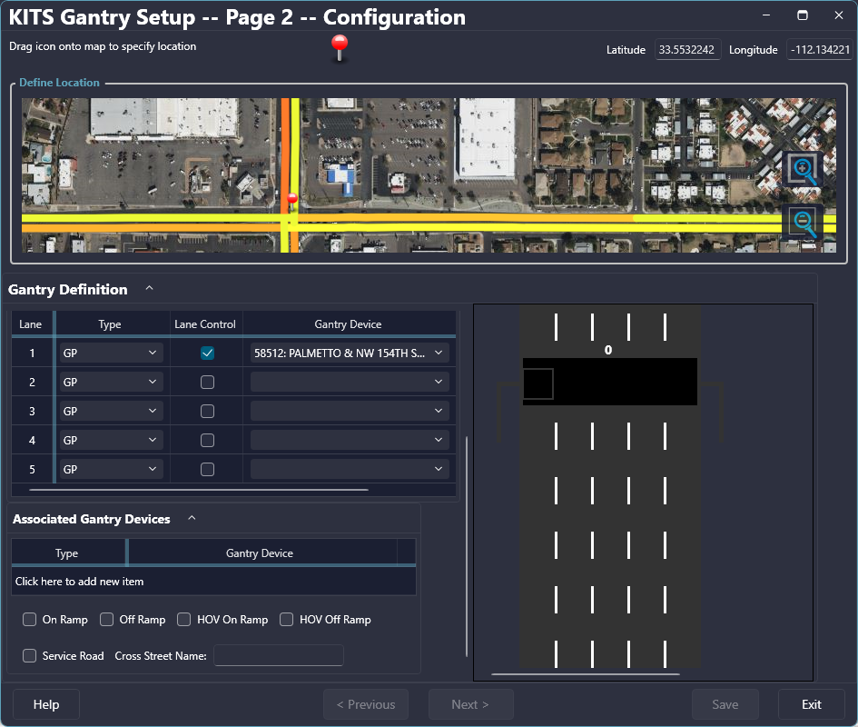
¶ Configuring Lane Controls
Lane Control DMS can be selected as individual DMS signs if no Center DMS is selected or if the Center DMS is not a multi-window DMS. To select a Lane Control DMS first enable the Lane Control option by checking the Lane Control checkbox. After, select the desired DMS from the list of defined signs. Each lane must have their own unique DMS selected.
If the selected Center DMS is defined as a multi-window DMS, the options for selecting individual Lane Controls will be disabled. The rendered Gantry on the right side of the wizard will show if there are Lane Control windows defined for that DMS.
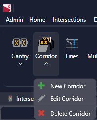
¶ Corridor Definitions (ATM | Corridor)
The Corridor Definition form allows the user to configure Parameters, Gantries, and Alignment of a corridor. The Corridor Definition form can be accessed from the ATM ribbon tab.
- ATM Tab -> Corridor
¶ Corridor Parameters
The Corridor Parameters can be modified within this section of the form.
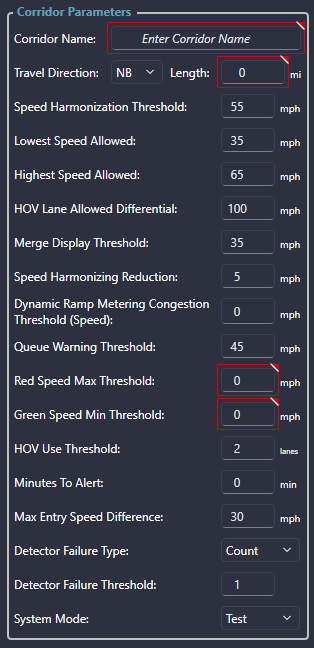

| Field | Description |
| Corridor Name | Sets the name of the corridor |
| Travel Direction | Sets the direction of travel for the corridor |
| Length | Sets the overall length of the corridor |
| Speed Harmonization Threshold | Sets the speed below which an automatic speed harmonization scenario will activate |
| Lowest Speed Allowed | Sets the lowest allowed posted speed limit within the corridor |
| Highest Speed Allowed | Sets the highest allowed posted speed limit within the corridor |
| HOV Lane Allowed Differential | Sets the maximum allowed speed limit difference between the HOV lanes and the General Purpose lanes. (A value of 100 means no differential limit is applied.) |
| Merge Display Threshold | Sets the minimum speed allowed before a merge arrow will display in a single lane |
| Speed Harmonization Reduction | Sets the factor for which speeds will be reduced when a speed harmonization is activated. Example: Given a Speed Harmonization Threshold of 55 MPH, a factor of 5 MPH would give speed limits of 55, 50, 45 etc; a factor of 10 MPH would give speed limits of 55, 45, 35, etc. |
| Dynamic Ramp Metering Congestion Threshold (Speed) | Sets the speed below which Dynamic Ramp Metering will activate |
| Queue Warning Threshold | Sets the speed below which an automatic queue warning scenario will activate |
| Red Speed Max Threshold | Sets the speed below which a lane will render as red |
| Green Speed Min Threshold | Sets the speed above which a lane will render as green Note: A speed between the Green and Red Thresholds will render as yellow. |
| HOV Use Threshold | Sets the number of lane closures needed at a gantry for the HOV lanes to convert to General Purpose use |
| Minutes To Alert | Set the number of minutes that an alert will activate for a future scheduled manual scenario |
| Max Entry Speed Difference | Sets the maximum speed reduction allowed for the first gantry in the corridor. |
| Detector Failure Type | Detector Failure is evaluated at each detection location, as either a percent of detectors or as a count of detectors. |
| Detector Failure Threshold | Sets the value at which all speed information for a particular location is ignored due to missing data from too many detectors. |
| System Mode |
Sets the mode of a corridor:
|
¶ Gantry Order
The Gantry Order section of the form is where gantries are added and arranged within a corridor.
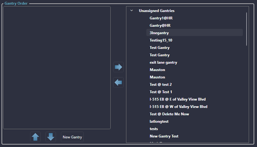
| Field | Description |
| Left Gantry Column | Lists the gantries within the corridor with starting gantry as the top most |
| Right Gantry Column | Lists all gantries that are not within the corridor |
| Remove Gantry Button (Arrow Pointing Right) | Removes the selected gantry from the corridor |
| Add Gantry Button (Arrow Pointing Left) | Adds the selected gantry to the corridor |
| Shift Upstream Button (Arrow Pointing Up) | Move the selected gantry towards the start of the corridor |
| Shift Downstream Button (Arrow Pointing Down) | Moves the selected gantry towards the end of the corridor |
| New Gantry Button | Launches the Gantry Wizard |
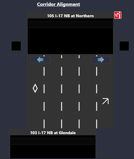
¶ Corridor Alignment
The Corridor Alignment section allows gantries with a corridor to be aligned properly to ensure the appropriate continuation of lanes. The user can select the left and right arrows to make the necessary adjustments for proper lane alignment.