¶ Section Definition (Intersections | Sections | New/Edit/Delete)
Use the Section Definition form to input a new section or view/edit existing section data.
.bmp)

| Parameter | Description |
| Short Name | is the abbreviated section name (up to 8 characters) used to identify sections throughout KITS. |
| Section ID | is the read-only identification number assigned to the current section by KITS. |
| Long Name | is the descriptive section name (up to 30 characters). |
| Region | allows the user to assign the section to a pre-defined region from the drop-down list. To add a section to a new region, the region must first be defined on the Region form. |
| Zone | allows the user to assign the section to a zone (engineering) |
| Scheduling Failure Threshold |
defines the percentage (between 1 and 100) of non-responding intersections that will cause a section’s scheduled plan to be overridden by standby. Default = 30 percent |
| Scheduling Recovery Threshold |
defines the percentage (between 1 and 100) of non-responding intersections that will cause a section’s scheduled plan to stop being overridden by standby. Default = 25 percent |
¶ Adding Intersections to a Section
To add an intersection, highlight the intersection name in the Intersection List box and click Add, or double-click on the intersection name in the Intersection List box.
The intersection will be transferred to the Added Intersection box while remaining in the Intersection List box. Hold down the CTRL or SHIFT keys while selecting from the list to highlight multiple intersections. Click Add and the selected intersections will be added.
To filter the Intersection List, enter up to the first 4 characters of the intersections you are looking for in the search key. The list will automatically update based on each character input, and display intersection names where either cross street matches the search key input.
¶ Removing Intersections from a Section
To remove an intersection, highlight the intersection name in the Added Intersection box and click Remove, or double-click on the intersection name in the Added Intersection box. The intersection will be removed from the Added Intersection box. Hold down the CTRL or SHIFT keys while selecting from the list to highlight multiple intersections. Click Remove and the selected intersections will be removed.
¶ Viewing and Editing Time-of-Day Intersection Assignments
To view or edit the time-of-day intersection assignments, highlight an intersection in the Added Intersection box and click TOD Assignments. KITS displays the Intersection Reassignment form (shown below) from which you can view and edit the intersection’s time-of-day section assignments.
.jpg)

This feature is currently unavailable in KITS .
¶ Printing a section definition
Pressing the printer button at the top of the form will print the section data as shown below.

.bmp)
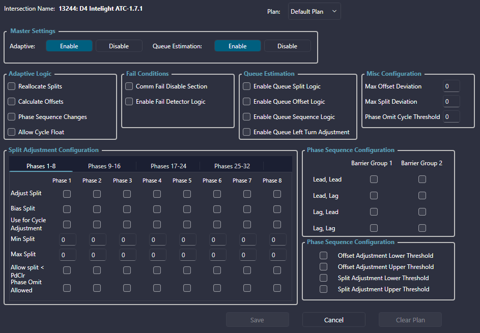
¶ Intersection Parameters (Adaptive | Intersection Parameters)
This page gives the user access to the intersection specific adaptive parameters. The desired intersection must be selected prior to opening this page. Notice the intersection asset number and name in the upper left.

¶ Configuring Intersection Parameters
The user can either edit the parameters for the Default plan or select a specific plan from the Plan dropdown as shown below.

¶ Parameter Descriptions
The parameters on this page are as follows:
| Parameter | Description |
| Operation | allows the user to Enable or Disable Adaptive mode for individual intersections in the Adaptive section. |
| Adaptive Logic | allows the user to determine if the intersection will Reallocate Splits, Calculate Offsets, support Phase Sequence Changes, or Allow Cycle Float. |
| Deviation Configuration | allows the user to define values for the Max Offset Deviation and Max Split Deviation. |
| Split Adjustment Configuration | allows the user to determine if each phase will adjust it's split, have a bias for that split, use the phase for cycle adjustment, or Allow Oversize Ped. |
| Phase Sequence Configuration | allows the user to configure the sequence for the two Barrier Groups. The available configurations are Lead Lead, Lead Lag, Lag Lead, Lag Lag. |
¶ Section Parameters (Adaptive | Section Parameters)
This page gives the user access to the section specific adaptive parameters. The desired section must be selected prior to opening this page. Notice the section name in the upper left.

¶ Configuring Section Parameters
The user can either edit the parameters for the Default plan or select a specific plan from the Plan dropdown as shown below.

¶ Parameter Descriptions
The parameters on this page are as follows:
| Parameter | Description |
| Cycle Adjustment Parameters | allows the user to define values for the Unsaturated and Saturated Phase Utilization, Minimum Number of Intersections Below and Above, and the Minimum Time that a Plan must be active. |
| Incremental Cycle Adjustment Parameters | allows the user to Enable Cycle Adjustment for the Section and define the Cycle Increment, Min Cycle Time, and Max Cycle Time. |
| TOD Schedule Adjustment Parameters | allows the user to Enable Plan Switching Adjustment for the Section and define the Earliest Start of the next TOD Plan and Latest End of the next TOD Plan. |
| Phase Sequence Parameters | allows the user to define values for Heavy and Light Phase Utilizations and the Comparative Difference Factor. |
| Split Adjustment Parameters | allows the user to define values for the Max Split Increment and Deviation. The user can also click the Copy button to copy the Split Deviation to all of the intersections within the section. |
| Offset Parameters | allows the user to define values for the Max Offset Increment and Deviation. The user can also click the Copy button to copy the Offset Deviation to all of the intersections within the section. |
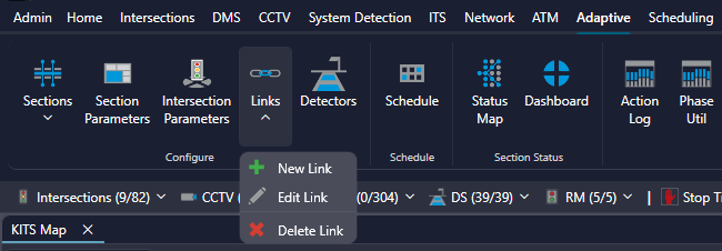
¶ Link Definition (Intersections | Links | New/Edit/Delete)
The Link Wizard gives the user the ability to create and edit adaptive links between intersections. The Link Wizard can be launched from multiple places within the Kits Ribbon including:
- Intersections -> Links -> Edit Link
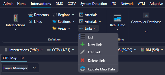

- Adaptive -> Links -> Edit Link

After selecting Link Definition from the menu, the Link Wizard window will appear.
The following instructions on how to interact with the map are shown:
- Click two intersections to create a link between them
- Click the same intersection twice to create a null link for Kadence
- Click an existing link to edit
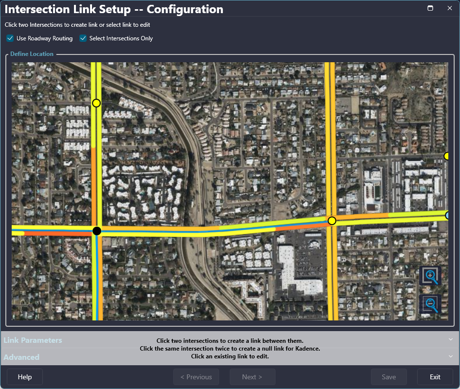

When creating a new link, after selecting two intersections, the corresponding dots become enlarged and the Link Parameters section is revealed. In addition to the Link Definitions, the parameters section also contains the Adaptive and Bluetooth Parameters.
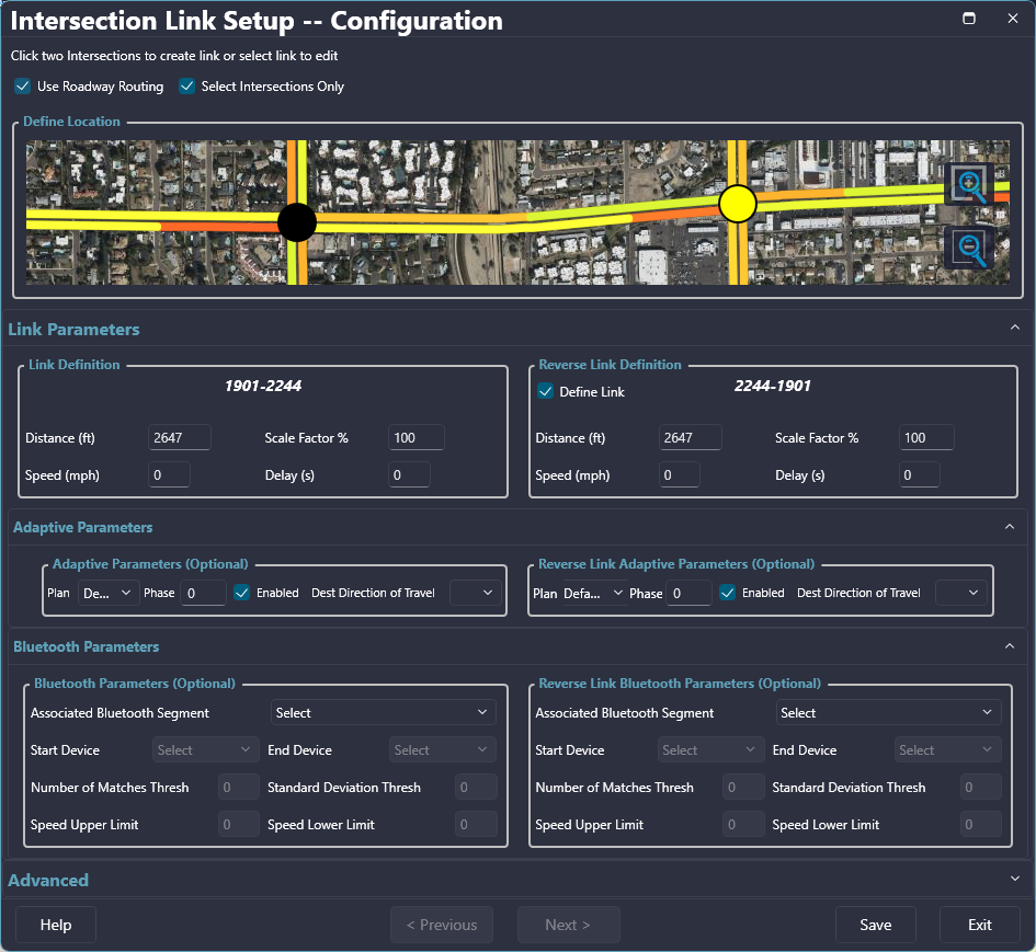

¶ Configuring Adaptive Parameters
Within the Adaptive Parameters a user may adjust the associated Plan and Phase for a give Link.

The Plan dropdown contains plans 1 - 40.

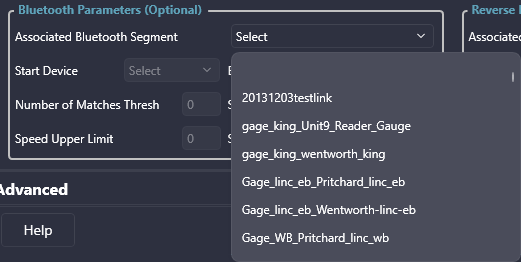
¶ Configuring Bluetooth Parameters
The Bluetooth Parameters section contains dropdown menus and fields for configuring the selected link.
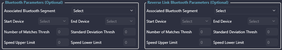

The Bluetooth fields are disabled by default until a Bluetooth Segment is selected from the dropdown menu as shown below.

Once configuration is completed, select Save and Exit the Wizard.
¶ Parameter Descriptions
The parameters on this page are as follows:
| Parameter | Description |
| Link Name | Is used to identify the link throughout KITS (up to 20 characters). |
| Distance (ft) |
Is the total length (between 1 and 32,000 feet) of the link. Automatically calculated during Link creation. Default = 1000 feet |
| Scale Factor % |
Sets the percentage of total volume (between 0 and 100 percent) that is counted for each detector in the link. Default = 100 percent |
| Speed (mph) | Specifies the default travel speed (between 1 and 100 mph) over the link. |
| Delay (s) |
Is used by the Route Preemption server to determine if traffic, or another factor, must be considered in the estimation of travel time between intersection nodes. The delay time (values between 0 and 32,000 seconds can be entered) is compared with the calculated link travel time from the free-flow speed and distance of the link. The larger of the two values is selected as the link travel time for use in route preemption. Example: 1000 ft / 35 mph (50.54 ft/sec) |
| Plan / Phase | Customize Link Phases for a specific Plan or Default Plan |
| Bluetooth Segment | List of available predefined Bluetooth Segments for associating to the selected Link |
| Start/End Device | List of available devices to assign at the start and end of segment |
| # of Matches Thresh | Threshold for number of matches found in the selected segment |
| Std Deviation Thresh | Deviation from number of matches threshold |
| Speed Upper / Lower Limit | Range in which vehicle data is analyzed |
¶ Detectors (Adaptive | Detectors)
The Adaptive Detectors page gives the user the ability to define adaptive detectors and the associated parameters that are used by Kadence. The desired intersection must be selected prior to opening this page. Notice the intersection asset number and name in the upper left.
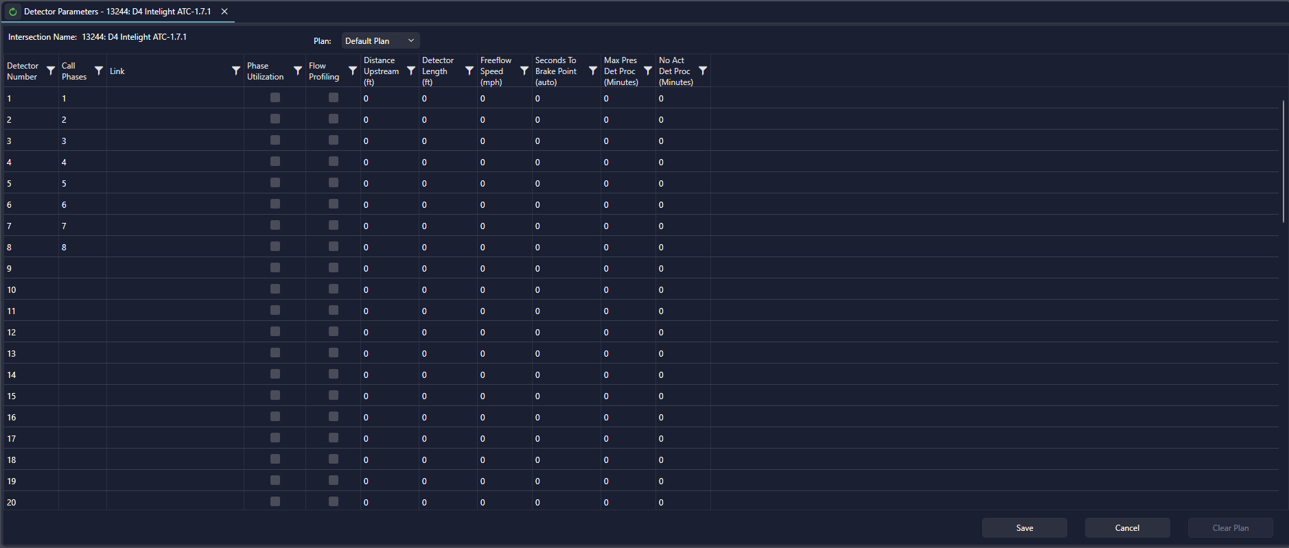

¶ Configuring Adaptive Detectors
To configure Adaptive Detectors the intersection of interest must first have links to other intersections defined. Once links have been defined, they become available in the dropdowns under the Link column.
¶ Parameter Descriptions
The parameters on this page are as follows:
| Parameter | Description |
| Detector Number | is the number of the detector used by Kadence. |
| Link | contains dropdowns with all of the Links defined for the selected intersection for defining which detector to use. |
| Phase Utilization | allows the user to configure the detector for Phase Utilization. |
| Flow Profiling | allows the user to configure the detector for Flow Profiling. |
| Distance Upstream | is the distance between the detector and the intersection. |
| Detector Length | is the physical length of the detector. |
| Freeflow Speed | is the speed that cars are assumed to be driving in low traffic conditions. |
| Seconds To Brake Point | is automatically calculated from other fields. |
| Call Phases | the phase being called by the detector |