¶ Device Definition Wizard
The device definition wizard is used for many types of devices, including Intersections, DMS, CCTV/VID, Adaptive Intersection Link, Road Segment, Gantry, Detector Station, Ramp Meter, Beacon, Road Weather Information System (RWIS), and Highway Advisory Radio (HAR). The device definition wizard can be accessed from the Add Device button on the Map ribbon menu tab (which is visible only when a Map is open). Shortcuts to the wizard for a specific device type can be found on the ribbon menu tab relating to that device. Please use the links above for more information about defining a given device type.
Other device types which may be added to or defined in KITS include ATM Corridors and Multi-Window DMS; these do not use the same device definition wizard. The linked pages explain how to access those forms.
¶ Intersection and Detector Definition (Intersections | Intersections | New/Edit/Delete)
The Intersection Wizard form allows the user to add new intersections and edit existing intersections. The Intersection Wizard can be accessed from multiple places.
- Intersections -> New Intersection
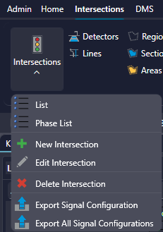
- Map (ribbon menu) -> Add Device

- Map (actual) -> right click -> Add New Device -> Intersection


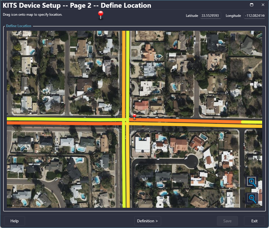
¶ Defining Intersection Location
When adding a new intersection, the location can be set by using the third option above, right clicking on the map to open the Add New Device Wizard. The location can also be set or edited from the 'Define Location' form. If it is a new intersection and a pin has not been placed, click and drag the pin at the top of the form to the desired location. If a pin has already been dropped, it can be relocated by clicking on it and dragging it to the desired location.

| Field | Description |
| Zoom In | Zooms the map in towards the center of the map view |
| Zoom Out | Zooms the map out |
| Latitude | Latitude of the pin's location |
| Longitude | Longitude of the pin's location |
| Help | Opens the help file for the 'Intersections Wizard' |
| Cancel | Cancels the intersection changes/creation |
| Previous | Goes to the previous page of the New Device Wizard (Page 1 is only accessible when Add New Device is used to open the wizard) |
| Next | Goes to the next page of the Intersection Wizard |
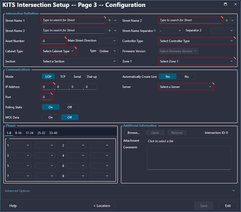
¶ Configuring an Intersection
An intersection is configured in Page 3 of the Intersection Wizard. This allows the definition of an intersection's required attributes with the required fields outlined in red. After completing the definition entry for an intersection, the Save button will be enabled allowing the user to finalize the intersection and close the Intersection Wizard. If Previous or Exit is selected before saving, any data entered will be lost.

| Field | Description |
| Street Name* | First street name of an intersection; start typing the name of a street to reveal the list of already defined street names. If the name does not exist select the green 'Plus' button to the right of the text field to add the name. |
| Street Name 2* | Second street name of an intersection; start typing the name of a street to reveal the list of already defined street names. If the name does not exist select the green 'Plus' button to the right of the text field to add the name. |
| Street Name 3 | Third street name of an intersection (optional); start typing the name of a street to reveal the list of already defined street names. If the name does not exist select the green 'Plus' button to the right of the text field to add the name. |
| Street Name Separator (1 & 2) | Defines the symbol that will be used to separate the street names when the intersection is listed |
| Asset Number* | Sets the Asset Number of an intersection for identification |
| Controller Type* | Selects the Controller Type from the available drop down menu of controller types |
| Cabinet Type* | Selects the Cabinet Type from the available drop down menu of cabinet types |
| Section | Selects the Section the intersection will be added to (optional) |
| Zone 1 | Sets the Zone that the intersection will be assigned to. It is a required field, but uses the default zone unless otherwise selected. |
| Mode | Sets the mode that is used for communication (IP, Serial, Dial-up); IP requires a line (can be created with auto feature); Serial requires a Line creation and Baud Rate definition; Dial-up requires a Line creation, Phone Number, and Baud Rate definition |
| IP Address | Defines the IP Address of the intersection, can be a predefined line or a line created via the 'Automatically Create Line' option |
| Port* | Sets the port number for communication |
| Drop Address | Sets the drop address (defaulted to 1) |
| Polling State | Sets the Polling State to on or off |
| Automatically Create Line | Activates the 'Automatically Create Line' feature for IP communication. When active, the defined IP Address will be used to create a line; when inactive, a predefined line can be selected in the communication section. |
| Line | Sets the communication line to a predefined line |
| Phone | Sets the phone number for Dial-up communication |
| Baud Rate | Sets the Baud Rate for communication (defaulted to 9600 for IP) |
| MOE Data | Sets collection of MOE Data to on or off Default = On |
| Phases | Sets the Phase mnemonics from available drop down menus |
| Attachment | Allows attachment of one file of the following file formats: .xlsx, .xls, .xml, .txt |
| Comment | A text field; The entry is included on the Excel Export file for the intersection. |
| Advanced Fields | |
| Zones (2-6) | Allows the intersection to be assigned to up to 6 zone categories; zones 2-6 are optional and can be blank. |
| Failure Threshold | The number of consecutive polls for which the central system receives no response before the intersection is considered "failed". Default = 5 |
| Retries | The number of attempts to poll the intersection after it has been determined to be failed the first time. Default = 5. |
| Overlaps | Sets the Overlaps for the intersection |
| * Minimum required attributes for an intersection to successfully be created. | |
¶ Detectors Configuration Page
¶ Detector Configuration Tool
The Detector Configuration Tool is a powerful resource for traffic engineers, providing them with the ability to update and fine-tune detector settings for intersections. Located within the Definitions section under the Intersections Tab, this Configurations page offers a user-friendly interface for managing detector configurations. With features such as filtering, adaptive detector auto-import, bulk editing, grouping, and search capabilities, this tool empowers traffic engineers to efficiently customize and optimize detector settings for accurate traffic data collection and analysis.
¶ Key Features:
Intersection Selection and Update:
Within the Configurations page, traffic engineers can select a specific intersection to update and adjust its detector settings. This streamlined process allows for targeted configuration modifications tailored to the unique characteristics and requirements of each intersection.
Flexible Filtering Options:
A filter at the top of the Configurations page enables engineers to narrow down the view and focus on specific types of detectors. With filter options including All Detector types, System/Count/Local/Speed Trap, ATSPM, Kadence (Adaptive), and TMC, engineers can efficiently locate and modify the properties relevant to their specific needs.
Adaptive Detector Auto-Import:
The configuration tool automatically imports configured adaptive detectors from the adaptive detectors table. This intelligent feature saves time and effort for traffic engineers by seamlessly integrating adaptive detector configurations into the overall detector settings.
Save and Revert Changes:
After making adjustments to the configuration grid, engineers have the option to save the new grid, preserving their modifications. Additionally, a revert feature allows engineers to discard any changes made and restore the most recently saved configuration.
Efficient Row Clearing:
The clear button on the configuration tool acts as a convenient row-clearing function. By selecting one or multiple rows (using shift-click for a section of rows and ctrl-click for individual rows), engineers can quickly clear them all at once. However, it's important to note that saving the changes is still required after clearing a row to apply the modifications.
Robust Search Functionality:
The tool offers a full-text search feature at the top of the grid, enabling engineers to search for specific parameters or values within the configuration. This functionality simplifies the process of locating and modifying specific settings, enhancing overall efficiency and productivity.
Grouping Rows by Column Values:
To facilitate data analysis and organization, engineers can click and drag column headers to the top of the grid, utilizing the "Drag a column header and drop it here to group by that row" row. This grouping capability helps visualize and analyze data by grouping rows based on their values in a specific column.
Manual Column Filtering:
Located in the top-right corner of the grid, engineers have the ability to manually filter columns using the filter button. This functionality allows for further data refinement and customization, ensuring that only relevant information is displayed.
¶ Benefits for Traffic Engineers:
Configuration Customization:
The Detector Configuration Tool empowers traffic engineers to customize and fine-tune detector settings based on the unique requirements of each intersection. This level of configuration customization ensures accurate and reliable traffic data collection, leading to more precise analysis and informed decision-making.
Time and Effort Savings:
By offering streamlined features such as filtering, bulk editing, grouping, and search capabilities, the tool saves valuable time and effort for traffic engineers. These efficiency-enhancing functionalities enable engineers to navigate and modify detector configurations swiftly and accurately, increasing productivity and effectiveness.
Data Analysis and Insights:
With the ability to search, group, and filter data, traffic engineers gain deeper insights into the detector configurations and their impact on traffic data collection. By efficiently organizing and analyzing this information, engineers can identify trends, patterns, and anomalies, facilitating data-driven decision-making and improved traffic management strategies.
