¶ Overview
Use the Timing Values form to view the real-time controller timing values for a selected intersection. The timing values will automatically update once per second.
To access Timing Values from the Intersections tab, select 'Timing Values' from the Real-Time drop down menu and then choose an intersection from the selection dialog, by scrolling or searching. Timing values for a selected intersection may also be accessed from the right click menu of an intersection icon on the map or intersection name in the Layer Manager on the map.
Double clicking on an intersection icon on the map will also open Timing Values for that intersection. Note: a double click on the map may open the Classic Timing Values form rather the new Timing Values. An option in the Advanced Settings in the Admin tab determines which version is opened.
When viewing Timing Values as a docked form, a user can easily switch to viewing timing values for a different intersection by clicking the reselect icon on the Timing Values tab. This opens a selection dialog, allowing a different intersection to be chosen.
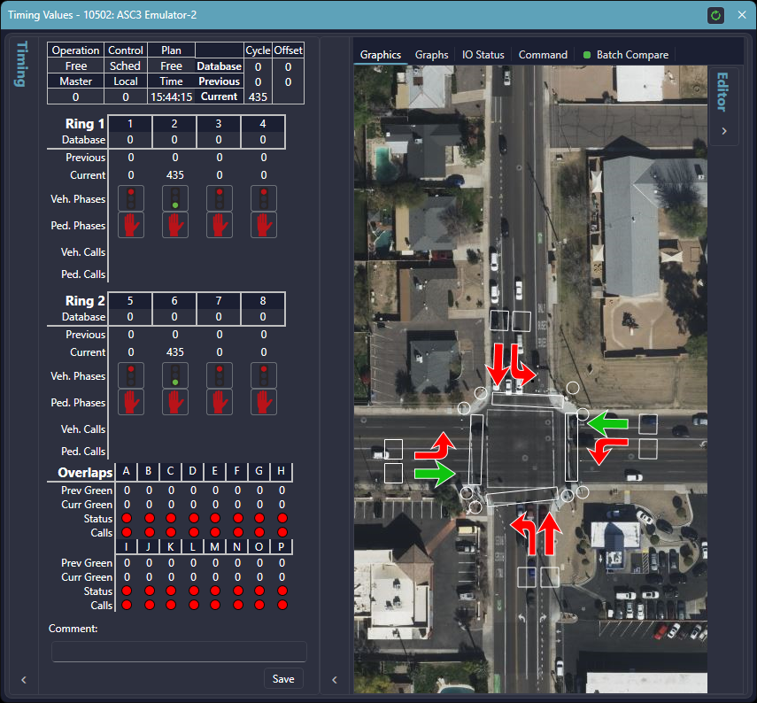

| Field | Description |
| Status | The status of the selected intersection controller (online, communications failure, flash, conflict, or coordination fail) |
| Operation | Indicates the current operation status of the selected intersection controller (local manual, nominal, not available, police control, railroad preempt, emergency vehicle preempt, and local TBC) |
| Plan | The timing plan that is currently being executed |
| Master Timer | The master timer value of the selected intersection controller |
| Local Timer | The local cycle timer value of the selected intersection controller |
| Time | The current time reported by the controller |
| Timing Cycles | Displays the total cycle length and offset defined in the database for the active plan, the previous cycle length and offset the controller reported, and the current cycle length the controller is reporting |
| Timing Information | Displays the active rings and phases of the current plan that is being executed by the controller |
| Graphics | Graphically based representation of the current state of the intersection as well as an editor to add and remove intersection graphics |
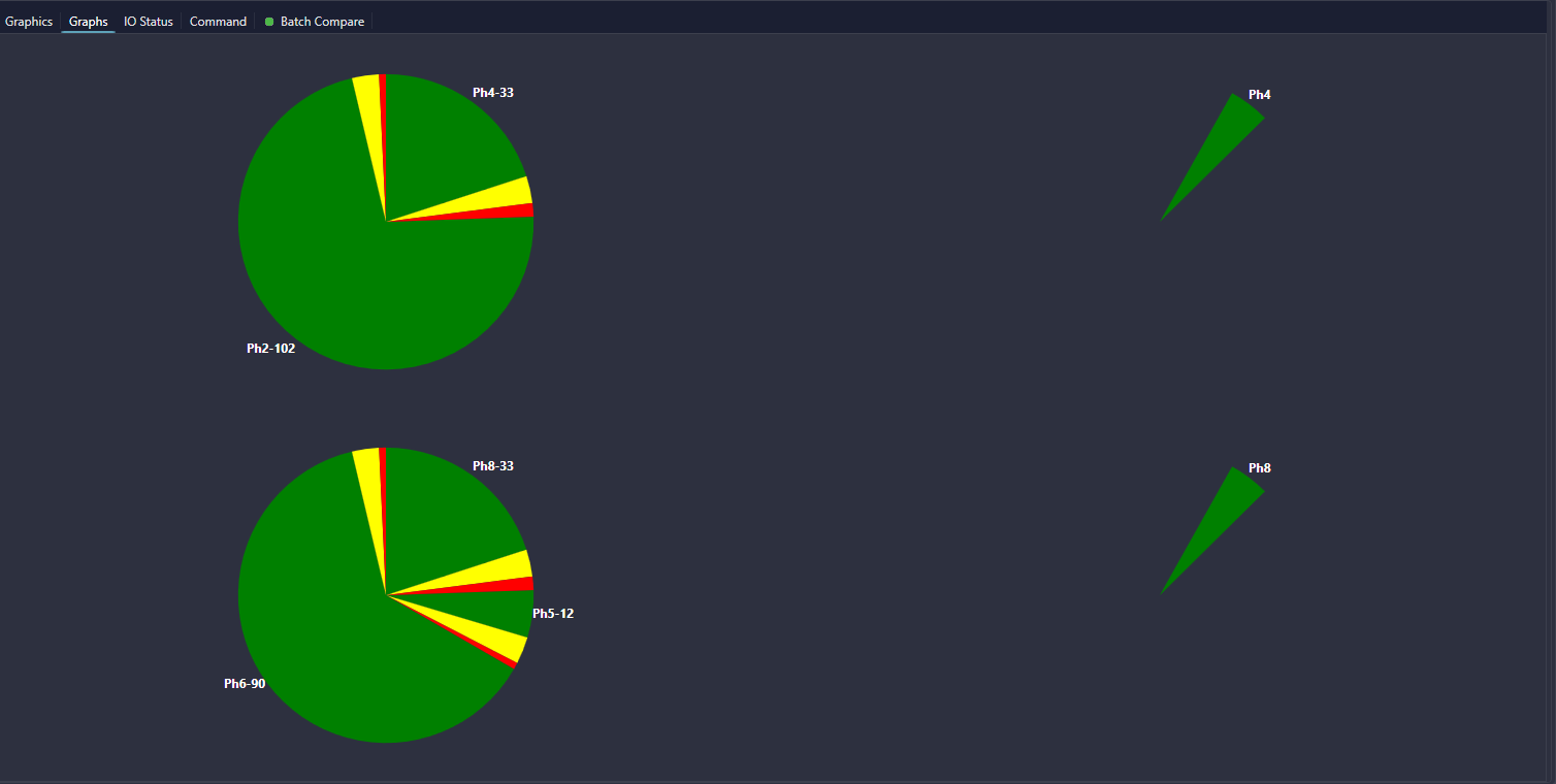
| Graphs | Shows which portion of the cycle length each phase occupied |
| IO Status | Shows active/inactive state of Special Functions and other I/O pins of the intersection |
¶ Timing Information
This shows the current status of the controller for the selected intersection. The Timing Information form is capable of showing the status of up to four rings. Each ring shows the phases that are active for the current plan that is being executed by the controller.
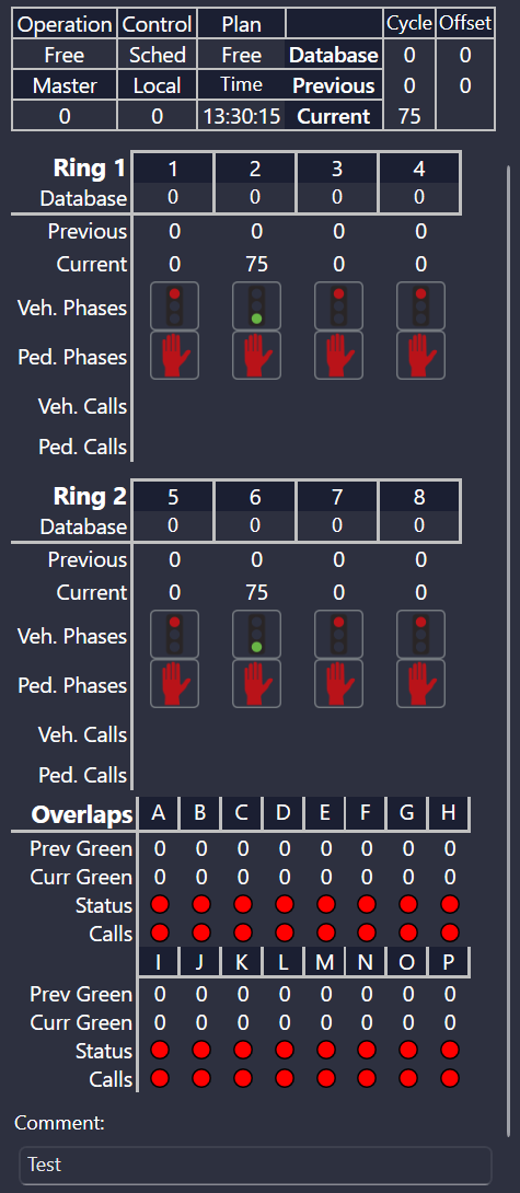
| Field | Description |
| Phase Mnemonic | The current phases within a ring with the phase number and abbreviated description of that phase |
| Database | The defined length of each phase within a cycle |
| Previous | The previously reported length for each phase within a cycle |
| Current | The current reported length for each phase |
| Vehicle Phases | A visual representation for the current status of the vehicle phases |
| Ped. Phases | A visual representation for the current status of the pedestrian phases |
| Vehicle Calls | A visual representation for the current status of the vehicle detectors associated with the phase |
| Ped. Calls | A visual representation for the current status of the pedestrian push button associated with the phase |
| Overlaps | A visual representation for the current status of each overlap. Previous and current green times are also available for all overlaps. |
¶ IO Status
Allows the user to view all Special Functions and Detectors for the selected intersection. When detectors and Special Functions are not active, they are plain black text. When Special Functions and Detectors are active they are highlighted.
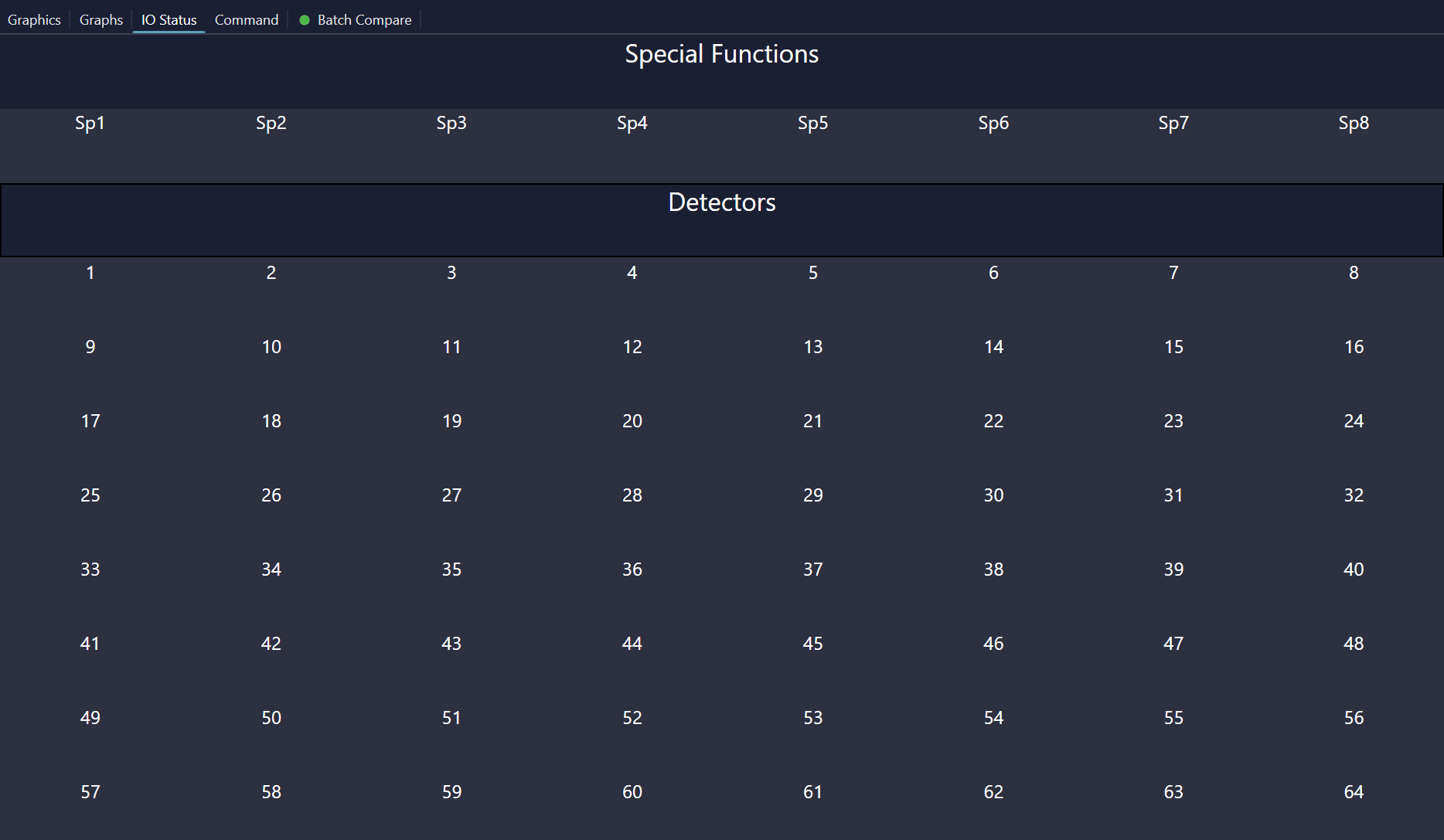
| Field | Description |
| Special Functions | Shows which special functions are currently active |
| Detectors | Shows which detectors are currently active |
¶ Graphs
Allows the user to view a graphical representation of the portion of the cycle length each phase occupied.
¶ Graphics Editor
Allows the user to add/delete/edit graphics and associate them with phases defined in the intersection.
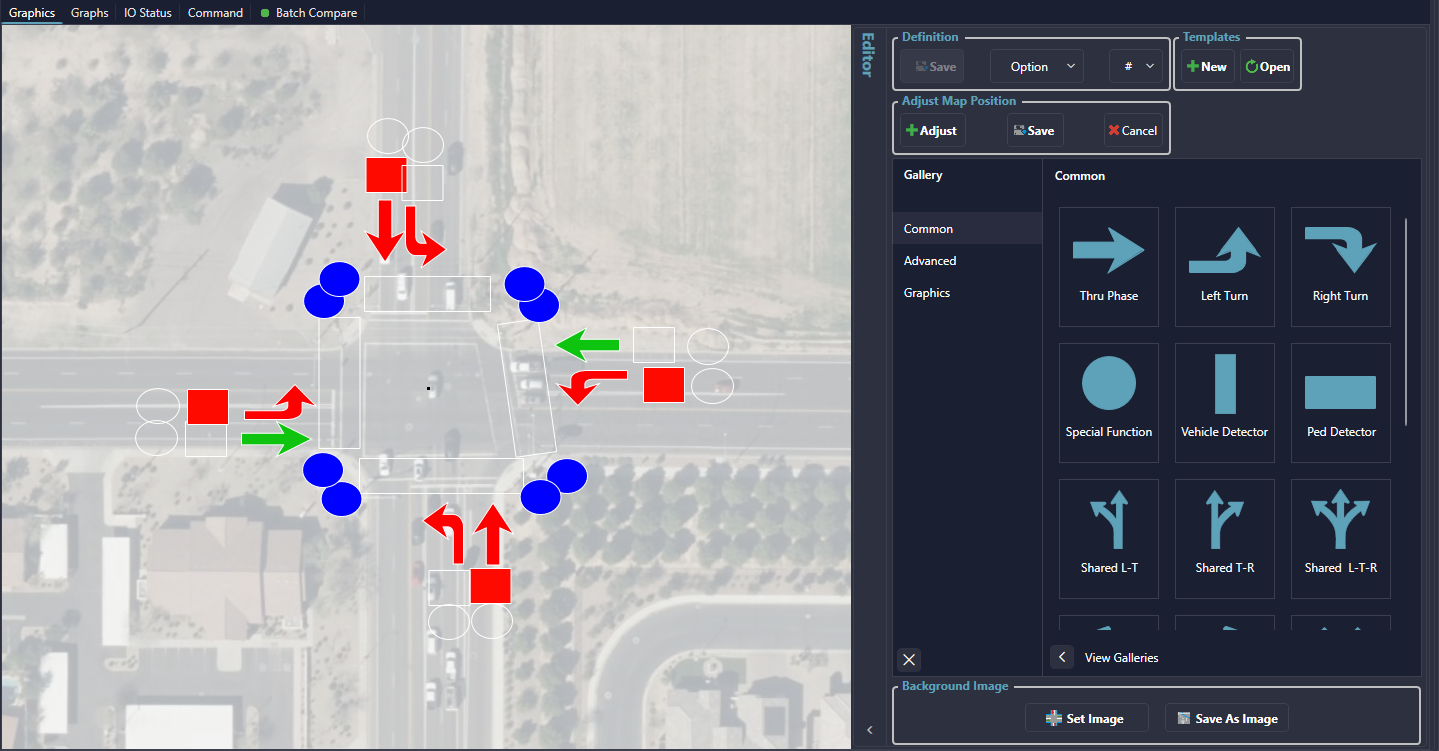

| Field | Description |
| Definition Section | Defines what sequence within a phase number the graphic will be associated with |
| Templates | Allows placed graphics to be added as a template or the option to load the graphics placement from a stored template |
| Gallery | Contains a palette of commonly used graphics for intersection representation and a palette of advanced graphics for intersection representation |
| Background Image | Allows users to set or clear a .jpg as the background image. By default, graphics will use the background image from the map tiles. |
¶ Adding graphics
Graphics can be added to an intersection to give a visual representation of the current intersection status. To add graphics, open the editor within the graphics tab of the Timing Values form. Once the editor is opened, locate the desired graphic from either the Common palette of graphics or the Advanced palette of graphics. After locating the desired graphic, left click and drag that graphic to the area of the intersection and release the graphic to place it. Once a graphic has been placed the size can be adjusted by dragging the outlined corners of the graphic. The graphic may also be rotated by left clicking on the clockwise arrow near the graphic and dragging it to the desired degree of rotation.
Once a graphic has been added, it may be defined to a sequence option and phase number, such as 'Vehicle Phase 1'. This is done by first selecting the sequence option from the 'Option' drop down menu. Once an option has been selected, the phase number can be selected from the '#' drop down menu.
¶ Adding and Clearing Background Images
To add a background image to use in place of the default map image, click the 'Set Image' button on the bottom of the image gallery. This will open a dialog displaying all of the available images under the specified image path (this is specified on the settings page under the 'Paths' section and is called 'Intersection Aerial Image Path').
To clear a background image, click the 'Clear Image' button and the background will revert to the default map image.
¶ Deleting graphics
Graphics can be deleted from an intersection by first opening the 'Graphics Editor' form. Once the editor has been opened, simple select the desired graphic to be deleted and press the delete key on the computer's keyboard.
¶ Saving Changes
To save any changes made to the graphics of an intersection, open the Graphics Editor and select the 'Save' button in the upper left corner. Any changes that are not saved will be lost when the Timing Values form is closed.
¶ Creating Templates
To create a template of the current graphics layout, simply select the 'Add' button from the 'Graphics Editor' form and a 'Save Template' menu will appear. To save the template enter a name into the 'Name' field and then select the 'Save' button directly to the right of the field. The template can be canceled by selecting the 'Cancel' button.

¶ Right Click Menu
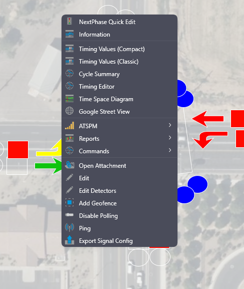
While the 'Graphics Editor' form is open, a right click menu becomes available. From this menu the user can show/hide a grid pattern over the view of the intersection, undo a change, redo a change, or save any changes made to the intersection graphics.
¶ Graphics Templates
Allows the user to load a graphics template to an intersection. This helps to reduce the time in setting the graphics for an intersection by having commonly used graphics layouts stored as templates. To access the templates, select 'View' button from the graphics editor.


| Field | Description |
| Load | Loads the currently selected template |
| Delete | Deletes the currently selected template |
| Close | Closes the scrolling view of available templates |
| Directional Arrows | Cycles through the available templates |
¶ Selecting a Template
To select a Template for either loading or deleting there are multiple ways to cycle through the available Templates. The first option is the use a scroll wheel on the mouse. The second option is to use the left and right arrows located at the bottom of the form.
¶ Load Template
After a Template is selected, it can be loaded by selecting the 'Load' button.
¶ Delete Template
After a Template is selected, it can be deleted by selecting the 'Delete' button.